Run of Record v6

Caption: V6.4 complete with marking sticker and knurled knobs.
This day marks the 1-year anniversary since the start of the “Run of Record” series of entries, and it is also where I plan to leave it. As you will see in the rest of this entry, I feel that I have perfected the design to a point of satisfaction. Of course, one can keep iterating, but at some point, one has to say: “This is it, this is the final one.”
After the failure that was v3, v4, and v5, I decided to restart from a blank canvas. I created a new CAD file, and I started remodeling the entire protractor. This was done partly from memory and partly from the engineering drawings I created from the CAD of v2.
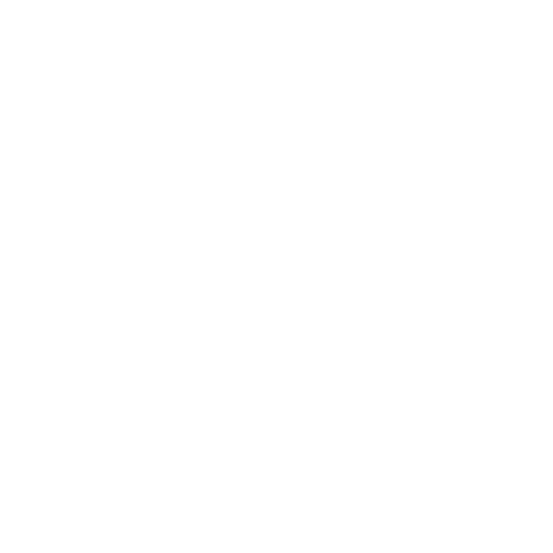
Caption: Some of the engineering drawings from v2 that I used as references.
This has several advantages for a mostly non-mechanical project such as this one. Keep in mind these things really only apply to a product CAD and not to some complex mechanical engine. If you need advice modeling that, go find a professional mechanical engineer who has actually studied this stuff in college.
Cleaning up messy angles and dimensions
Rethinking unnecessarily complex geometry
Adding additional adjustments for user-friendliness
Simplifying dimensions for engineering drawings
After making all the necessary changes, I moved on to creating a set of engineering drawings, as well as actually printing the model and adjusting tolerances. This allows me to create what I like to call a “Packet.” Since the next steps of my plan involve reaching out to people about the project, this will act as the one .zip file I can send to someone who wants to know more about it, specifically if they are trying to manufacture it…
My packet contained the .step file, engineering drawings in .pdf, a few images of the printed object, and the .ai file containing the new markings I have made. The files were named as such:
Zero Pivot Protractor Marking V6.ai
Zero Pivot Protractor Showcase Image.png
Zero Pivot Protractor Showcase Image 2.png
Zero Pivot Protractor V6.4.2 Model.step
Zero Pivot Protractor V6.4.pdf
Caption: Zero Pivot Protractor Showcase Image.png
Version: 6.1-6.2
Summary: Redesign of slider into knob shape for better ergonomics.
Main Benefit: Firm hold and smoother operation when sliding.
Main Deficit: Pen marks are not consistent with drawing angle.
Potential Improvements: Modifications to the shapes of edges that will be traced by the pen.
Notes:
Aside from remodeling and cleaning up in general, I also modified the handle
By studying v1.2, I noticed that the lone-screw handle on it is significantly easier to use than the rounded-sector shape that I had been using
The handle on v6.1 is a rounded-cylinder with knurled edges
Attached to the arms with a screw, gives unexpected feature of locking a measurement by turning the handle.
V6.2 added a notch on the screw handle for lining up measurements

Caption: Close-up top view of version 6.2 CAD model, showing the notched, rounded-cylinder handle.
Version: 6.3-6.4
Summary: Downward slanted drawing edges to prevent pen marks on the protractor.
Main Benefit: Prevents pen tips scraping the side of the protractor, creating unwanted markings.
Main Deficit: Not really any!
Potential Improvements: Last version!!
Notes:
V6.3 adjusted tolerances for 3D printing
Added a tiled edge to the drawing edges, giving space for the pen to draw without touching the protractor’s edges
New placement and design for marking stickers, inner arm has two positions, corresponding to the red and black rows of numbers on near the outer arm slider. One set is used to draw obtuse angles, where the inner arm is retracted, and the other is used to draw acute angles, where the inner arm is extended.

Caption: Close-up side view of version 6.4 CAD model, showing the tiled edge.