
Run of Record v3, v4, v5
When I began designing what I now call version 3, I had good intentions—since I know how hard undercuts seen in v2 would be to make in real life, I wanted to create a version that would be more friendly to manufacture with CNCs, making the part out of aluminum and brass—now, I have no intentions of manufacturing v3, v4, or v5.
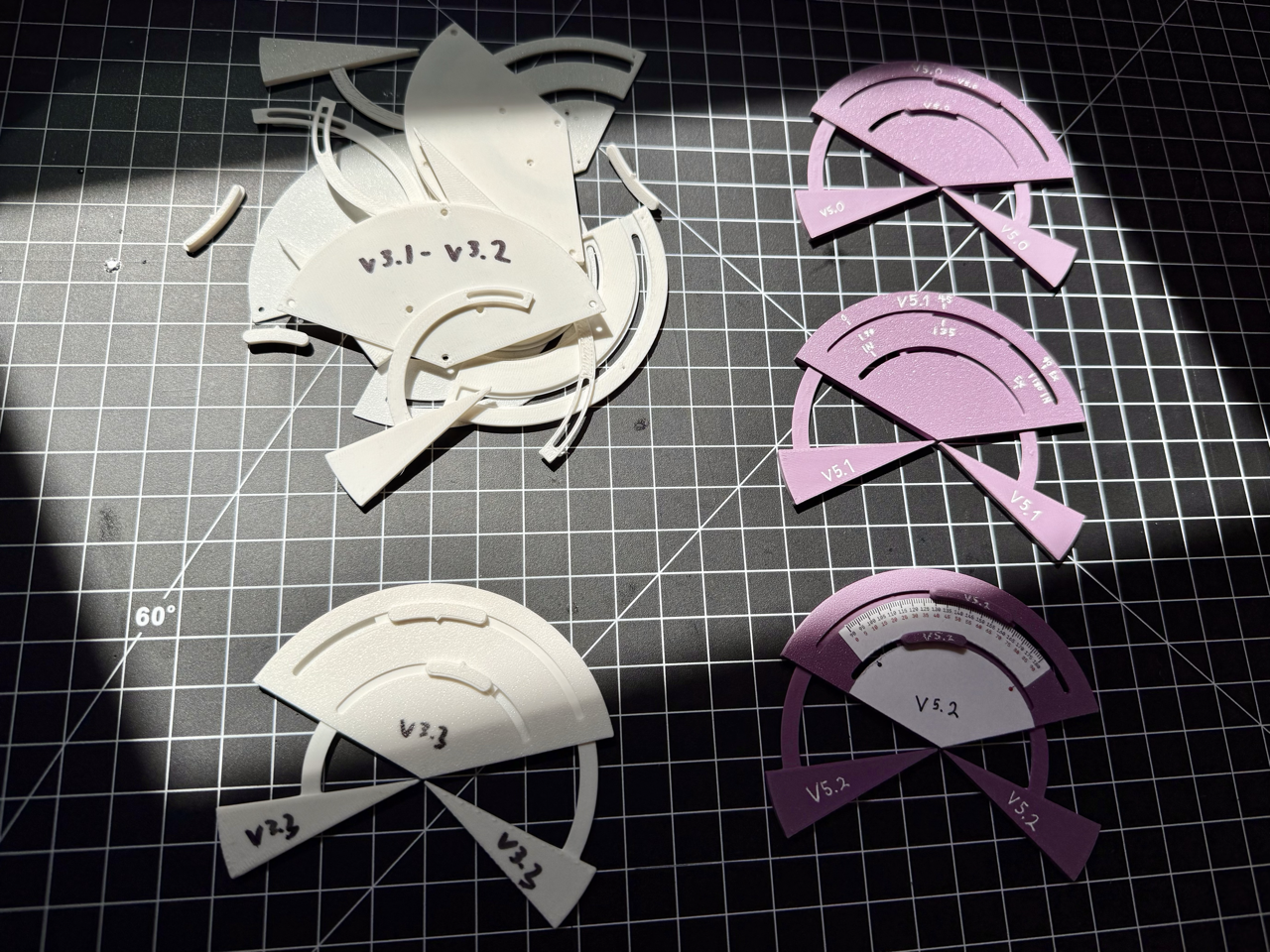
Caption: Iterations of v3 and v5.
This Run of Record is the hall of shame: v3 barely moved, v4 never left the drawing board, and v5 simply didn’t work. But failure is part of the process. Could I have hidden these versions and renumbered the next ones? Sure. But I’d rather show the whole trail.
Version: 3.x
Summary: Triple-layered plating design secured with screws.
Main Benefit: Ease of manufacturing in the main body.
Main Deficit: Difficulties in assembly, barely moves properly, and the arms are near impossible to manufacture.
Potential Improvements: More layers to form an T-shaped guide rail.
Notes:
Redesigned with the idea of sandwiching the slider inside the main body.
3 distinct layers attached together with ultra-thin screws.
Sliding mechanism catches too easily due to printing issues on the slider arm due to its suspended section needing supports.
Hard to assemble due to the thin plates and more parts.
V3.3 had 2 layers which made it easier to assemble, but the other issues remained.
Version scraped.
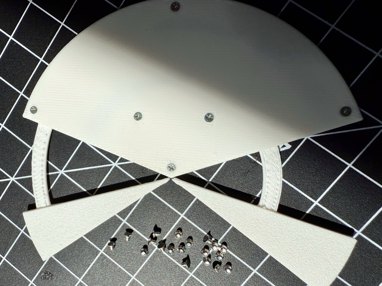
Caption: Close-up bottom view of v3.3 showing screws and printing artifacts on slider arms.
Version: 4.x
Summary: Concept for a locking mechanism based on a visible spring-bearing system.
Main Benefit: Tactile and visual snapping of the bearing at zero and full extension along with locking of the inner arm at 0° and 90°.
Main Deficit: Complex assembly and unrealistic geometry.
Potential Improvements: Non-mechanical methods of snapping and position control.
Notes:
V4 and v5 both tried to find a locking mechanism for the inner slider at zero and full extension, which would solve the complex numbering system issue.
Based off of v2, this version added 2 spring-bearing mechanisms and a matching groove on the inner arm.
New marking system relies on the inner arm having binary extension—zero or full, which would correspond to either the top or bottom number on the outer arm’s readout.
Geometry limitation would have caused the internal spring chambers to cave in.
Version scraped.

Caption: Parts I bought in hopes of designing such a mechanism.
Version: 5.x
Summary: New locking mechanism for the inner arm using 3 micro magnets.
Main Benefit: Less mechanical complexity while achieving the same objective.
Main Deficit: Complex geometry and weak snapping.
Potential Improvements: Larger custom-shaped magnets.
Notes:
Better mechanism with less mechanical complexity overall.
3 magnets are grouped together in 2 places on the main body and one place on the inner slider for a total of 9.
Micro magnets are hard to handle and attach rigidly to anything.
Only possible improvement is to create a custom-shaped magnet in the shape of an arc, which would be beyond the budget of this project.
Version scraped.

Caption: Bottom view of version 5.2, showing magnet groups.