
Run of Record v1
This is the first in what I plan to be a series of revision-style articles, acting as a change log and a progress update on the 3D model of the protractor project.
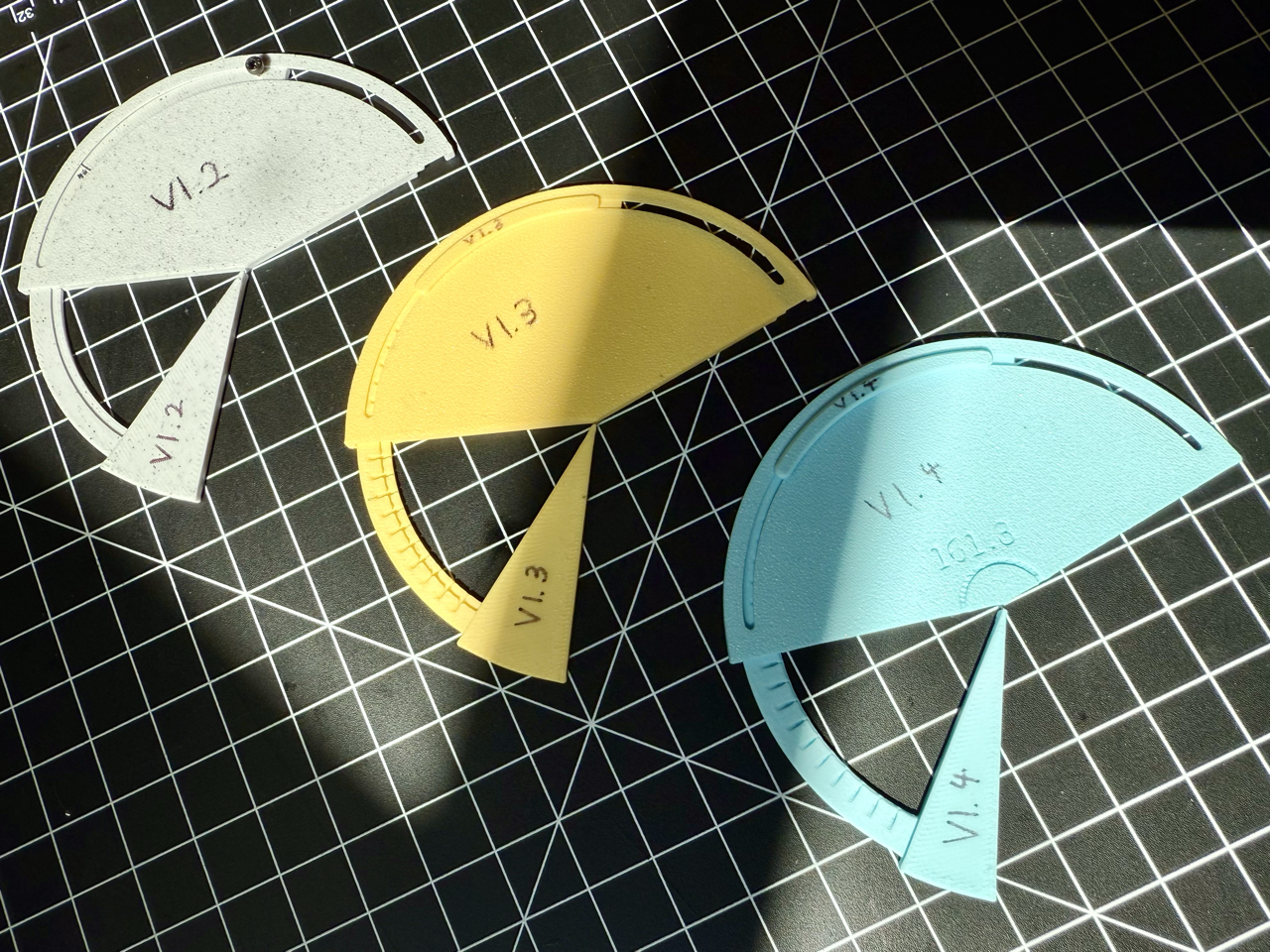
Caption: Iteration v1.2, v1.3, and v1.4.
Version: 1.2
Summary: External pivot design, stability issues at full extension, lack of rail guidance.
Main Benefit: Eliminates the need for a central pivot, allowing for sharp angles.
Main Deficit: Unstable, it falls apart if you look at it wrong.
Potential Improvements: Additional screws along the slider arm.
Notes:
First printed version after the original pilot
Utilizes a screw to allow the smaller pointer arm to slide
Expands the central pivot structure outwards
Does not expand to full 180°
Tends to separate vertically from main body with nothing to support it as it extends
3D printed plastic is too flexible, twisting the outside rim of the main body allows the screw to fall out as the rim is too thin

Caption: Close-up photo of version 1.2 falling apart.
Version: 1.3
Summary: Stability compensation with elongated 3D printed handles.
Main Benefit: More stable, does not fall apart as easily.
Main Deficit: Arm still separates vertically when extended further out.
Potential Improvements: Addition of internal rails.
Notes:
Extended the screw’s cross-sectional shape along the arc, forming the slider
Slight clearance issues along the slider, there is too much friction
Slider limits the motion of the arm to 90°
Due to 3D printing, the tip of the arm comes out blunt and rounded, making the angle hard to draw

Caption: Cross section of version 1.3 CAD model, showing the slider.
Version: 1.4
Summary: Internal guide rails in “<<” configuration.
Main Benefit: No longer separates vertically when extended.
Main Deficit: Rail connection loose and unreliable, the angle hard to draw due to plastic flexing.
Potential Improvements: Clearance or shape changes in guide rail.
Notes:
Addition of internal guide rails, giving the arm support directly from the main body as well as through the slider
Guide rail developed by looking at common drawer rail designs “-|”, optimized for 3D printing with all angles at 45° as so: “<”
Enlarged the tip of the arm into a small rectangle, calibrated to cause the 3D printer to overshoot, resulting in a sharper tip
The angle of the main body is arbitrary, if I want to ensure a 90° angle, I can adjust the slider’s arc length to compensate
The angle I set to a value that holds significance only to me, as a sort of inherent “watermark”

Caption: Top view of version 1.4 CAD model, showing the enlarged arm tip.